Model
SLS-4/SLS-4M Antenna Switching Matrix
Model
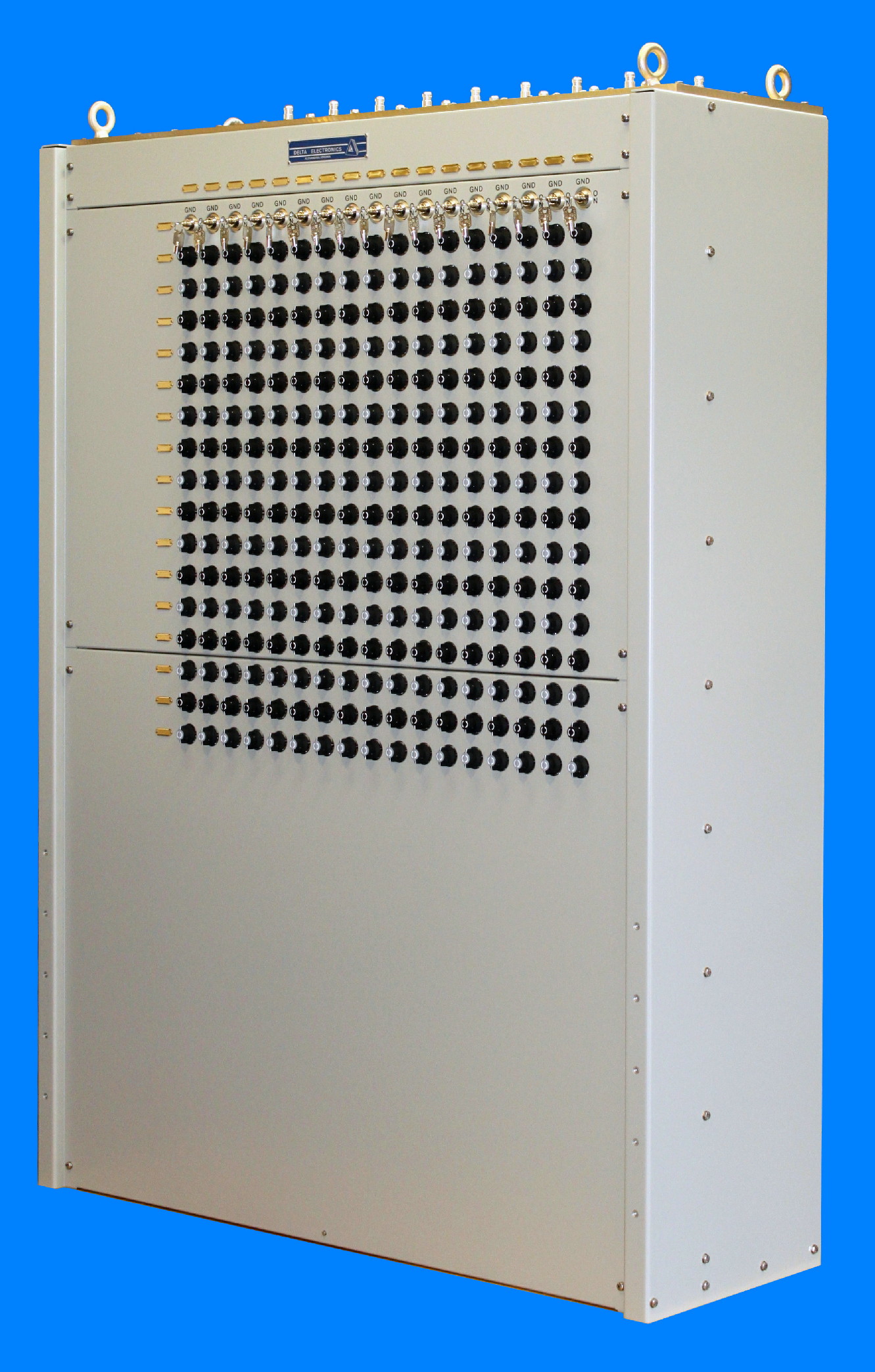
SLS-4M(17 X 17) Strip Line Switch
Model
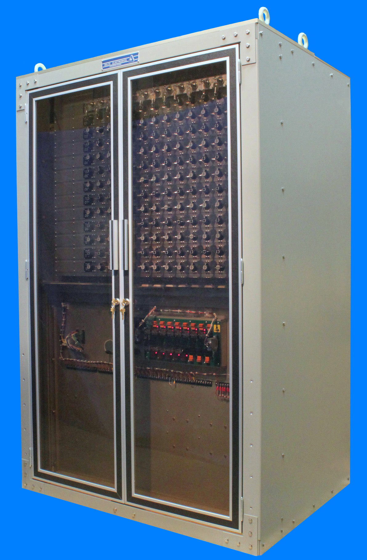
SLS-4M(12 X 13) Strip Line Switch
with Optional Doors
Introduction
The Delta Electronics Model SLS-4 Strip
Line Switch is a manually or
remotely controlled 50 Ohm switch matrix for connecting any of a number
of transmitters to any of a number of antennas. The SLS-4 is ideally
suited for use with 10 kW average power transmitters and with 3:1
maximum VSWR antennas. The switch design provides a compact system with
excellent power rating, low insertion VSWR, low insertion loss, and
high isolation characteristics.
The design of the switch makes
it inherently impossible to
connect
more than one transmitter to one antenna or to connect more than one
antenna to one transmitter. An interlock circuit that exactly
duplicates
the RF circuit operates to remove power from the RF circuit prior to
switching. At the completion of the switching sequence, the interlock
circuit is rerouted and reconnected to protect the new RF circuit. An
indicator circuit provides a dry contact closure for each transmitter
to antenna connection for remote indication of the switch status.
The switch is available in
either a manually operated version
(SLS-4) or a motorized version (SLS-4M). All manually operated switches
incorporate a motorized wiring harness and can be easily converted to
motorized operation.
Description
The Model SLS-4 Strip Line Switch
comprises a
matrix of horizontal transmission lines (rows), vertical transmission
lines (columns) and crosspoint switching elements at each row-column
intersection. Each crosspoint consists of row and column leaf springs
and a rotor contact. In the Thru position, RF power flows through the
crosspoint to the adjacent row leaf spring and adjacent column leaf
spring, and the grounded rotor contact shields the transmission lines
from each other. When the rotor contact is rotated 90 degrees to the
Turn position, the conductive shoulders of the rotor contact connect
the row transmission line to the column transmission line and perform
the desired switching. The rotor contact also disconnects the adjacent
row and column leaf springs from the switched circuit. This action
removes transmission line stubs from the RF circuit and prevents
paralleling of inputs or outputs.
All auxiliary interlock and
indicator switching is performed
by a
wafer switch deck incorporated in the manual switch or motor actuator
located on the rear of each switch module. The rotor contact is
mechanically linked to the manual switch or motor actuator. Thus, the
rotation of the rotor contact automatically performs the auxiliary
switching.
The protective interlock
circuit exactly duplicates the RF
circuit through the switch. The timing of the interlock switching
prohibits the occurrence of "hot" RF switching. The first 30 degrees of
rotation opens the established interlock path removing RF power from
the crosspoint. The second 30 degrees of rotation accomplishes RF path
switching. The last 30 degrees of rotation establishes the interlock
circuit to the new RF path and permits power to be applied.
The SLS-4 also provides a
bussed row and column indicator
circuit for remote matrix status. The indicator circuit switch closes
when the crosspoint is in the Turn position and opens when the
crosspoint is in the Thru position.
The SLS-4 provides the
capability for remotely controlled
switching of all crosspoints. The switch may be initially equipped for
manual operation of all crosspoints, or for motorized operation of some
or all crosspoints. All motorized crosspoints are capable of manual
override operation. Manual switch controls are accessible from the
front of the switch.
Configurations
The SLS-4 is available in either a
free-standing, self-supporting
cabinet or a rack mounting panel for installation in a standard 19" or
24" wide EIA equipment rack. The switch is constructed per customer
order to contain the number of inputs, outputs, and crosspoints
required for the particular application. Self-supporting cabinet
switches are available with sizes ranging from one column and one row
(1 x 1) to forty columns and thirty rows (40 x 30). Consult the factory
for applications requiring matrices larger than forty columns and
thirty rows. Rack mounted switches may have matrix sizes of up to eight
rows by four columns for the 19" rack-mounting version, and matrix
sizes of up to eight rows by six columns for the 24" rack-mounting
version.
The following basic
configurations are available. For each
configuration, inputs from transmitters may be assigned to either the
rows or columns and outputs to antennas may be assigned to either the
columns or rows, respectively, depending on the application and design
of the communication facility.
Configuration
A: This
configuration has the column
connectors on the top of the switch and the row connectors staggered on
opposite sides of the switch facing to the rear.
Configuration
B: The column
connectors are on the top
of the switch. All row connectors are located along one side of the
switch facing to the rear. The standard BL configuration defines the
row connectors on the left side of the switch when viewed from the
front. The optional BR configuration defines the row connectors on the
right side of the switch when viewed from the front.
Configuration
D: This
configuration defines a standard
19" or 24" wide EIA equipment rack-mounting switch. All row and column
connectors face to the rear.
Configuration
DSA: This
configuration, a modification
of Configuration A, double staggers the row connectors on opposite
sides of the unit to provide four vertical columns of row connectors.
This configuration is recommended for a switch with the row connectors
extended to top of switch using right angle rigid coax transmission
lines in order to minimize the cabinet depth.
Standard Features
Interlock Isolation Assembly
The SLS-4 includes the Model IIU
Interlock Isolation Unit to provide an isolated interlock interface to
the transmitters. The interlock circuit of the switch is a single wire
circuit with a common return. Since the interlock circuits of many
transmitters are above ground and may not be connected together via the
switch interlock harness, the IIU relays provide isolated interlock
switching for each transmitter. The IIU also provides an additional
contact closure to a common for each valid interlock circuit. This
contact closure may be monitored by a control system for remote
indication of the interlock circuit status.
Interlock Keylock Switches
The SLS-4 is equipped with
interlock keylock switches installed in the output interlock circuit.
The keylock switches provide positive lockout of the interlock circuit
and the corresponding RF output. The key can be removed only when the
keylock switch is in the open interlock circuit position. Each keylock
switch may be supplied with either different keying or identical
keying. Keylock switches are not supplied when the switch is equipped
with the optional key operated antenna grounding crosspoints.
RF Connectors
The standard RF termination is 1-5/8"
EIA male
flange. Optional terminations are 7/8" EIA male flange, Type LC
receptacle, Type LT receptacle, 7-16 DIN receptacle and Type N
receptacle. The switch may
be initially equipped with any combination of these connectors.
Modification kits are available for field conversion of these
terminations. Reducers to convert larger transmission lines to 1-5/8"
for switch interface are optionally available.
Optional Features
Key Operated or Automatic Antenna Grounding
The switch may be
equipped with a special row or column of grounding crosspoints that
ground each output terminal when the associated crosspoint is in the
Turn position. This feature allows an antenna to be grounded at the
switch for isolation during maintenance activities or for static
discharge when the antenna is not connected to a transmitter. With this
option, the row or column adjacent to the output terminals is equipped
with grounding crosspoints. These antenna grounding crosspoints may be
equipped with either key operated rotor assemblies for manual grounding
or with actuators for automatic grounding. The key operated grounding
crosspoints can only be manually operated and can only be operated
using the unique key for that crosspoint. The key can be removed only
when the crosspoint is in the antenna ground position. The motorized
antenna grounding crosspoints are controlled by the associated Model
MCU-8 or MCU-9 Matrix Control Unit to automatically ground the antenna
upon disconnection of the antenna from a transmitter.
Key Operated or Automatic Transmitter Grounding
The switch may be
equipped with a
special row or
column of grounding crosspoints that ground each input terminal when
the
associated crosspoint is in the Turn position. This feature allows a
transmitter to be grounded at the switch for isolation during
maintenance
activities. With this option, the row or column adjacent to the input
connectors is equipped with grounding crosspoints. These transmitter
grounding
crosspoints may be equipped with either key operated rotor assemblies
for
manual grounding or with actuators for automatic grounding. The key
operated
grounding crosspoints can only be manually operated and can only be
operated
using the unique key for that crosspoint. The key can be removed only
when the
crosspoint is in the transmitter ground position. The motorized
transmitter
grounding crosspoints are controlled by the associated Model MCU-8 or
MCU-9
Matrix Control Unit to automatically ground the transmitter upon
disconnection
of the transmitter from an antenna
Test Point
An additional row or column terminated
with a Type N connector may be
provided on the matrix to be used as a test point for antenna VSWR
measurements.
Row Extension Kits
When transmitter or
antenna coaxial cables connecting to the switch are located in ceiling
trays,
the switch may be equipped with right angle rigid coaxial transmission
lines on
the row connectors to extend these connectors to the top of each
switch.
Optionally, when coaxial cables connecting to the switch are located in
floor
cable trenches, the switch may be equipped with right angle rigid
coaxial
transmission lines to extend the row connectors to the bottom on the
switch.
These row extension kits are available in both 7/8” EIA and 1-5/8” EIA
standard
transmission line sizes.
Front and Rear Doors
On
special order, the SLS-4 may be equipped with custom plexiglass front
and louvered rear doors. When combined with the row extension option,
the front and rear doors provide a fully enclosed switch. The doors are
equipped with locks to restrict switch access. Door-open cabinet
interlock switches remove the transmitter RF voltages via the interlock
circuits upon opening either front door or either rear door.
Dummy Load
The SLS-4 may be supplied with dummy
loads as part
of the switch system. In certain instances, low power dummy loads may
be installed inside the matrix cabinet.
Trunking/Inverting
On special order, the SLS-4 may be
supplied with extra terminations to permit through trunking of either
rows or columns. Optionally, the SLS-4 may be inverted to locate the
column connectors on the bottom of the switch for applications
utilizing floor cable trenches for the coaxial cables.
Installation Services and Logistic Data
Installation services
and logistic data are available for the Model SLS-4 Strip Line Switch.
The installation services include site survey, system installation and
site acceptance tests. The logistic data includes provisioning data,
spare parts lists, factory training, reliability and maintainability
analyses, safety studies, and technical manual documentation. Most line
replaceable units for the switch are provisioned and assigned National
Stock Numbers.
Remote Control
Matrix Control Units
The SLS-4M may be remotely controlled
with either the Delta Model MCU-8
Matrix Control Unit or the MCU-9
Matrix Control Unit.
The MCU-8 and MCU-9 provide standard features such as
transmitter/antenna circuit display, interlock status display,
transmitter/antenna busy protection and unavailable transmitter/antenna
circuit protection. The MCU-8 provides remote control and a video
status display for a single switch up to forty inputs and forty outputs
and for multiple switch systems up to four sixteen input by sixteen
output switches. The MCU-9 provides remote control and a plasma panel
status display for a single switch up to sixteen inputs and sixteen
outputs and for dual switch systems up to eight inputs by eight outputs
each. The MCU-8 and MCU-9 are available with an EIA RS-232 or RS-422
serial data or Ethernet interface to a customer's control system or computer.
Serial Interface Assemblies
The MSSI
Medium Switch Serial Interface and the LSSI Large Switch Serial Interface
provide an EIA RS-232 or RS-422 serial data or Ethernet interface for remote control
and status
reporting of the Model SLS-4M. The MSSI is used with switch sizes up to
eight columns and eight rows and the LSSI is used with switch sizes up
to
sixteen columns and sixteen rows. A single printed circuit board
interface assembly includes microprocessor, random access memory,
programmable read-only memory, actuator interface circuits and serial
data interface circuits. The control and status command format is based
on the Model MCU-8C and Model MCU-9C serial interface format standard
for compatibility with computer control programs and drivers developed
for transmit matrix control and status via the MCU-8C or MCU-9C.
Matrix Control and Diagnostic Test Software
Remote control software
which provides control, status display and diagnostic testing of the
SLS-4 and MCU-8/MCU-9/MSSI/LSSI is also available. In addition to providing all the
basic control and status features of the MCU-8/MCU-9 units, the software
enhances the control capabilities by using mouse-driven equipment
selection routines and expands the display capabilities to include
large matrix schematic diagrams and equipment labels. The program also
provides diagnostic routines to automatically test remote matrix
operation capabilities and to isolate faults to the line replaceable
unit level. Preset switch configurations establishing multiple
transmitter/antenna connections may be defined, stored and
automatically implemented. All switch configuration changes, status
reports, and diagnostic test results may be logged on the system
printer. The software operates as a remote controller for
the SLS/MCU system. Thus, the personal computer may communicate with
the MCU using an RS-232 or RS-422 or Ethernet interface. Alternately, the switch
may be equipped with the MSSI/LSSI and a direct
RS-232/422/Ethernet data communication circuit established
between the computer and the switch.
Serial Data
Interface
The
standard serial interface is per RS-232 or RS-422 using ASCII
characters for
control and status information. The serial data format is compatible
with
computer programs developed for the Delta Model MCU-8C Matrix Control Unit,
Model
MCU-9C Matrix Control Unit, Model MSSI Medium Switch Serial Interface
or Model
LSSI Large Switch Serial Interface applications. Consult
factory for
optional
serial data formats or interfaces.
The
standard
serial interface characteristics are 7 data bits per character, one
start bit,
programmable one or two stop bits and programmable even or odd parity.
The baud
rate is switch selectable with standard data rates from 50 to 19,200.
The
serial input circuit provides a high input impedance and the serial
output
circuit is programmable for either active or tristate to enable serial
data bus
communication circuits.
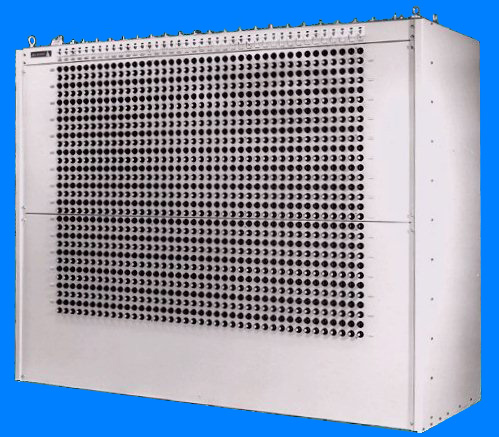
Model
SLS-4M(40 X 30) Strip Line Switch
SLS-4 SPECIFICATIONS
| Frequency Range: |
DC to 32 MHz
(Operation to 300 MHz available on special order.
Consult factory for extended frequency range performance
specifications.)
|
| Impedance: |
50 Ohms Coaxial
|
| Power Rating: |
30 kW Average, 100 kW Peak
Unity VSWR, 5000 Ft Maximum Altitude
(To determine the power rating for other values of
load VSWR, divide power rating by load VSWR. Consult factory for higher
altitude derating.)
|
| Insertion VSWR: |
1.10 maximum for matrix sizes up to 40 x 30
|
| Insertion Loss: |
Size Loss
10 x
10: 0.10
dB
16 x 16: 0.15 dB
20 x
20: 0.18
dB
30 x
30: 0.26
dB
40 x
30: 0.30
dB
(Insertion loss for all models at 32 MHz is 0.025
dB + N(0.004) dB. N equals the number of modules in the path. A 10 x 10
matrix has 19 modules in the longest path.)
|
| Cross Channel Isolation: |
70 dB Minimum
|
| Terminations: |
Standard: 1-5/8" EIA Male Flange
Optional: 7/8" EIA Male Flange
Type
LC Receptacle
Type
LT Receptacle
Type
7-16 DIN Receptacle
Type
N Receptacle
|
| Temperature: | Operating: 0şC to +50şC
Non-Operating: -62şC to +75şC
|
| Humidity: | 0% to 95% Noncondensing
|
| Size: |
Self-Supporting: 64.75" high (15 row max) x 17"
deep
Height increases by 2.0 inches for each row above
15. Width varies with number of columns. Depth increases to 30"
for 20 rows and greater. Contact factory for specific
size information
Rack Mounting: 19" or 24" wide standard EIA rack
panel x 12" deep. Height varies with number of rows.
|
| Weight: |
Size
Manual
Motorized
5 x 5:
140 lbs
161 lbs
10 x 11: 260 lbs
338 lbs
16 x 16: 450 lbs
575 lbs
20 x 20: 650 lbs
875 lbs
30 x 30: 1200
lbs 1650 lbs
40 x 30: 1820
lbs 2570 lbs
(Switch weight varies with options. The table
above gives approximate weights for some representative sizes of
self-supporting switches.)
|
| Accessories: |
Key Operated or Automatic Antenna/Transmitter Grounding
Built-In Dummy Loads
Interlock Keylock Switches
RF Connector Field Modification Kits
Row Connector Extension Kit
Front and Rear Doors
|
| Remote Control Options: |
Delta
Matrix Control Units - MCU-8 and MCU-9
Delta Serial Interface Assemblies - MSSI and LSSI
Delta Remote Control and Diagnostic Test Software for personal computer remote control.
|
For
additional information on any of our products, please contact Sales to
discuss your particular requirements:
Delta Electronics, Inc.
5730 General Washington Drive
P. O. Box 11268
Alexandria, VA 22312
|
Phone: (703) 354-3350
U.S. Toll Free: 1-800-8-DELTA-8 (1-800-833-5828)
Fax: (703) 354-0216
www.deltaelectronics.com
Email: sales@deltaelectronics.com |
The Delta Electronics logo is a registered
trademark of Delta Electronics, Inc.