
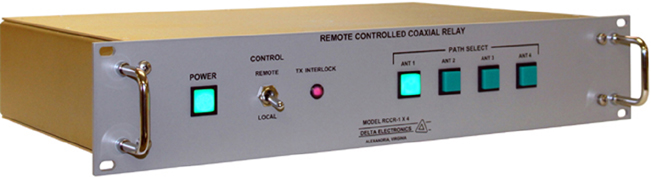
Model RCCR-1 X 4
Remote Controlled
Coaxial Relay
Control and Status Word Formats |
|
| A. |
Connect Command (Remote
Control System to RCCR-1 X 4): CR LF ADRS C T1 T2 A1 A2 X |
| B. |
Status Command (Remote
Control System to RCCR-1 X 4): CR LF ADRS S T1 T2 X |
| C. |
Status Response (RCCR-1 X 4 to Remote
Control System): CR LF ADRS S T1 T2 A1 A2 F M I PS ETB |
| D. |
Complete Status Command (Remote Control
System to RCCR-1 X 4): CR LF ADRS S A L L X |
| E. |
Complete Status Response (RCCR-1 X 4 to remote
Control System): CR LF ADRS S T1 T2 A1 A2 I F M PS ETB |
The characters are defined as follows: |
||
| CR | = |
ASCII Carriage Return |
| LF | = | ASCII Line Feed |
| ADRS | = |
Coaxial Switch Control Panel
Address (Switch Selectable); ASCII characters 0 - 9 and A - F (Factory set to ASCII 1) |
| C | = | Command Designator for Connect Message |
| S | = | Command Designator for Status Message |
| ALL | = | ASCII Character String Meaning ALL Transmitters |
| T1 | = | Most Significant Digit of Transmitter Number (always 0) |
| T2 | = | Least Significant Digit of Transmitter Number (always 1) |
| A1 | = | Most Significant Digit of Antenna Number (always 0) |
| A2 | = | Least Significant Digit of Antenna Number |
| F | = |
Fault Digit 0 = Fault 1 = Summary Fault 3 = Connection Fault |
| M | = |
Mode Digit 0 = Local Mode 1 = Remote Mode |
| I | = |
Transmitter Interlock Status Digit 0 = Open Interlock 1 = Valid Interlock |
| PS | = |
Coaxial Transfer Switch Power Supply
Status Digit Always 1 = Supply Normal |
| X | = | ASCII X to End Command Message |
| ETB | = | ASCII End of Transmission Block to End Status Response |
| Model and Name: | Model RCCR-1 X 4 Remote Controlled Coaxial Relay |
| RF Switching Configuration: | 1 Transmitter X 4 Antennas |
| Characteristic Impedance: | 50 Ohms |
| Frequency Range: | DC to 32 MHz |
| Insertion VSWR: | 1.05 Maximum |
| Insertion Loss: | 0.1 dB Maximum |
| Power
Rating
with Unity VSWR: (5000 Ft Maximum Altitude) |
2 kW Average/6 kW Peak |
| Cross Channel Isolation: | 90 dB Minimum |
| Switching Speed: | Less than 250 msec after operating a Path Select pushbutton switch or receiving a valid connect command |
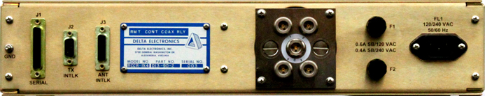
| RF Connectors: | Type N Receptacles for Transmitter and Antennas |
| RF Relay Contact Life: | >1 X 10⁶ operations |
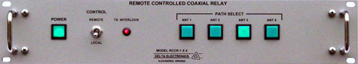
| Control: | Local:
Pushbutton Path Selection Remote: RS-232 or RS-422 Serial Data Interface |
| Local Status Display: | Illuminated pushbutton indicates transmitter/antenna RF connectivity and illuminated LED indicates transmitter interlock status |
| Serial Data Interface: | RS-232 or RS-422, baud rate selectable in standard increments from 50 through 19200 baud. |
| Error Detection: | Parity, framing and overrun error detection prevents faulty operation of coaxial relay |
| Remote Control Connector: | 25 Pin "D" Connector, DB-25P |
| Interlock Relay Contact Rating: | 90 VA |
| Dimensions and Weight: | 3.5" (89 mm) high by 19" (483 mm) wide by 12" (305 mm) deep, 10 pounds (4.5 kg) |
| Power Requirements: | 120
VAC, 50/60 Hz @ 0.5 Amps 240 VAC, 50/60 Hz @ 0.25 Amps |
| Temperature: | Operating:
0°C
to +40°C Storage: -30°C to +71°C |
| Delta Electronics, Inc. 5730 General Washington Drive P. O. Box 11268 Alexandria, VA 22312 |
Phone: (703) 354-3350 U.S. Toll Free: 1-800-8-DELTA-8 (1-800-833-5828) Fax: (703) 354-0216 www.deltaelectronics.com Email: sales@deltaelectronics.com |
| HOME | AM/FM/TV Products | HF/VHF/UHF Products |