
Model SLS-5/SLS-5M Antenna Switching Matrix
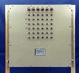
Model SLS-5M (6 X 6) Strip Line Switch
Introduction
The Delta Electronics Model SLS-5 Strip Line Switch is a manually or remotely controlled 50 Ohm switch matrix for connecting any of a number of RF sources to any of a number of RF loads. The SLS-5 is ideally suited for use in the HF band with 1 kW average power transmitters and with 4:1 maximum VSWR antennas. The switch may also be used in a multitude of DC to 400 MHz communication applications such as switching receive level signals from antennas, switching IF level signals between equipment, and switching transmit power signals. The switch design provides a compact system with excellent power rating, low insertion VSWR, low insertion loss, and high isolation characteristics.
The design of the switch makes it inherently impossible to connect more than one transmitter to one antenna or to connect one transmitter to more than one antenna. An interlock circuit that exactly duplicates the RF circuit operates to remove power from the RF circuit prior to switching. At the completion of the switching sequence, the interlock circuit is rerouted and reconnected to protect the new RF circuit. An indicator circuit provides a dry contact closure
for each transmitter to antenna connection for remote indication of the switch status.
The switch is available in either a manually operated version (SLS-5) or a motorized version (SLS-5M). All manually operated switches incorporate a motorized wiring harness and can be easily converted to motorized operation.
Description
The Model SLS-5 Strip Line Switch comprises a matrix of horizontal transmission lines (rows), vertical transmission lines (columns) and crosspoint switching elements at each row-column intersection. Each crosspoint consists of row and column leaf springs and a rotor contact. In the Thru position, RF power flows through the crosspoint to the adjacent row leaf spring and adjacent column leaf spring, and the grounded rotor contact shields the transmission lines from each other. When the rotor contact is rotated 90 degrees to the Turn position, the conductive shoulders of the rotor contact connect the row transmission line to the column transmission line and perform the desired switching. The rotor contact also disconnects the adjacent row and column leaf springs from the switched circuit. This action removes transmission line stubs from the RF circuit and prevents paralleling of inputs or outputs.
All auxiliary interlock and indicator switching is performed by a wafer switch deck incorporated in the manual switch or motor actuator located on the rear of each switch module. The rotor contact is mechanically linked to the manual switch or motor actuator. Thus, the rotation of the rotor contact automatically performs the auxiliary switching.
The protective interlock circuit exactly duplicates the RF circuit through the switch. The timing of the interlock switching prohibits the occurrence of "hot" RF switching. The first 30 degrees of rotation opens the established interlock path removing RF power from the crosspoint. The second 30 degrees of rotation accomplishes RF path switching. The last 30 degrees of rotation establishes the interlock circuit to the new RF path and permits power to be applied.
The SLS-5 also provides a bussed row and column indicator circuit for remote matrix status. The indicator circuit switch closes when the crosspoint is in the Turn position and opens when the crosspoint is in the Thru position.
The SLS-5 provides the capability for remotely controlled switching of all crosspoints. The switch may be initially equipped for manual operation of all crosspoints, or for motorized operation of some or all crosspoints. All motorized crosspoints are capable of manual override operation. Manual switch controls are accessible from the front of the switch.
Configurations
The SLS-5 is available in standard sizes of 4 inputs by 4 outputs (4 x 4), 6 inputs by 6 outputs (6 x 6), 8 inputs by 8 outputs (8 x 8), and 11 inputs by 11 outputs (11 x 11). Each of these sizes mounts in a standard 19" wide EIA equipment rack. The switch inputs are assigned to the rows and the switch outputs are assigned to the columns. All connectors face to the rear.
The SLS-5 is also available in a free-standing, self-supporting cabinet or as a rack mounting panel for installation in a 24" wide EIA equipment rack. Consult the factory for applications requiring matrices larger than 11 columns and 11 rows.
The SLS-5 may also be supplied in a custom configuration and enclosure qualified for military applications. The OK-261A/BRC Transmitter Antenna Switching Group, which comprises a 5 column by 6 row switching unit and pushbutton remote control unit, and the TM/CIS-2 Transmit Matrix/Control Interface System with a microprocessor-based remote control unit are shipboard qualified systems which meet DOD specifications for shock (MIL-S-901), vibration (MIL-STD-167), environment (MIL-E-16400), electromagnetic interference (MIL-STD-461) and enclosure (MIL-STD-108).
Standard Features
Interlock Isolation Relays
The SLS-5 includes relays to provide an isolated interlock interface to the transmitters. The interlock circuit of the switch is a single wire circuit with a common return. Since the interlock circuits of many transmitters are above ground and may not be connected together via the switch interlock harness, the relays provide isolated interlock switching for each transmitter. The relays also provide an additional contact closure to a common for each valid
interlock circuit. This contact closure may be monitored by a control system for remote indication of the interlock circuit status.
Interlock Keylock Switches
The SLS-5 is equipped with interlock keylock switches installed in the output interlock circuit. The keylock switches provide positive lockout of the interlock circuit and the corresponding RF output. The key can be removed only when the keylock switch is in the open interlock circuit position. Each keylock switch may be supplied with either different or identical keying.
RF Connectors
The standard RF termination is Type N female receptacle. Optional terminations are Type C and BNC receptacles. The switch may be initially equipped with any combination of these connectors. Modification kits are available for field conversion of these terminations.
Optional Features
Key Operated or Automatic Antenna Grounding
The switch may be equipped with a special row or column of grounding crosspoints that ground each output terminal when the associated crosspoint is in the Turn position. This feature allows an antenna to be grounded at the switch for isolation during maintenance activities or for static discharge when the antenna is not connected to a transmitter. With this option, the row or column adjacent to the output terminals is equipped with grounding crosspoints. These antenna grounding crosspoints may be equipped with either key operated rotor assemblies for manual grounding or with actuators for automatic grounding. The key operated grounding crosspoints can only be manually operated and can only be operated using the unique key for that crosspoint. The key can be removed only when the crosspoint is in the antenna ground position. The motorized antenna grounding crosspoints are controlled by the associated Model MCU-8 or MCU-9 Matrix Control Unit to automatically ground the antenna upon disconnection of the antenna from a transmitter.
Low Power Switching
On special order, the SLS-5 may be supplied with gold-plated row and column leaf springs for reliable received signal level or IF signal level switching.
Trunking
On special order, the SLS-5 may be supplied with extra terminations to permit through trunking of either rows or columns.
Remote Control
Matrix Control Units
The SLS-5M may be remotely controlled with either the Delta Model MCU-8 Matrix Control Unit or the MCU-9 Matrix Control Unit. The MCU-8 and MCU-9 provide standard features such as transmitter/antenna circuit display, interlock status display, transmitter/antenna busy protection and unavailable transmitter/antenna circuit protection. The MCU-8 provides remote control and a video status display for a single switch up to forty inputs and forty outputs and for multiple switch systems up to four sixteen input by sixteen output switches. The MCU-9 provides remote control and a plasma panel status display for a single switch up to sixteen inputs and sixteen outputs and for dual switch systems up to eight inputs by eight outputs each. The MCU-8 and MCU-9 are available with an EIA RS-232 or RS-422 serial data interface to a customer's control system or computer.
Serial Interface Assemblies
The SSSI Small Switch Serial Interface and the MSSI Medium Switch Serial Interface provide an RS-232 serial data interface for remote control and status reporting of the Model SLS-5M. The SSSI is used with switch sizes up to four columns and four rows and the MSSI is used with switch sizes up to eight columns and eight rows. The single printed circuit board interface assembly includes microprocessor, random access memory, programmable read-only memory, actuator interface circuits and serial data interface circuits. The control and status command format is based on the Model MCU-8C and Model MCU-9C serial interface format standard for compatibility with computer control programs and drivers developed for transmit matrix control and status via the MCU-8C or MCU-9C.
Matrix Control Software
Remote control software which provides control, status display and diagnostic testing of the SLS-5 and MCU-8/9 is also available. The software operates on an IBM-AT or compatible personal computer with VGA graphics. The software is available for use with a customer supplied personal computer or as part of a Delta supplied computer system. In addition to providing all the basic control and status features of the MCU-8/9 units, the software enhances the control capabilities by using mouse-driven equipment selection routines and expands the display capabilities to include large matrix schematic diagrams and equipment labels. The program also provides diagnostic routines to automatically test remote matrix operation capabilities and to isolate faults to the line replaceable unit level. Preset switch configurations establishing multiple transmitter/antenna connections may be defined, stored and automatically implemented. All switch configuration changes, status reports, and diagnostic test results may be logged on the system printer. Optional program modules provide control and status reporting of other communication station facilities including rotatable log periodic antennas, receive matrices, transmitters, receivers, and site security equipment.
The software operates as a remote controller for the SLS/MCU system. Thus, the personal computer may communicate with the MCU using an RS-232 or RS-422 serial data bus directly or via modems and telephone lines or radio circuits. Alternately, the switch may be equipped with a Matrix Interface Unit and a direct RS-232/422/423 or fiber optic data communication circuit established between the computer and the switch.
Installation Services and Logistic Data
Installation services and logistic data are available for the Model SLS-5 Strip Line Switch. The installation services
include site survey, system installation and site acceptance tests. The logistic data includes provisioning data, spare
parts lists, factory training, reliability and maintainability analyses, safety studies, and technical manual
documentation. Many line replaceable units for the switch are provisioned and assigned National Stock Numbers.
SLS-5 SPECIFICATIONS
| Frequency Range: | DC to 400 MHz |
| Impedance: | 50 Ohms Coaxial |
| Power Rating: | 4 kW Average, 20 kW Peak, DC to 32 MHz
1 kW Average, 10 kW Peak, 32 to 400 MHz
Unity VSWR, 5000 Ft Maximum Altitude(To determine the power rating for other values of load VSWR, divide power rating by load VSWR. Consult factory for higher altitude derating.) |
| Insertion VSWR: |
DC to 32 to
Size 32 MHz 400 MHz
4 x 4: 1.05 1.10
6 x 6: 1.05 1.10
8 x 8: 1.05 1.15
11 x 11: 1.10 1.20
(Insertion VSWR may be improved to 1.10 maximum, 32 to 400 MHz special order. Consult factory for improved VHF performance specifications.) |
| Insertion Loss: |
DC to 32 to
Size 32 MHz 400 MHz
4 x 4: 0.10 dB 0.15 dB
6 x 6: 0.10 dB 0.15 dB
8 x 8: 0.10 dB 0.20 dB
11 x 11: 0.10 dB 0.25 dB |
| Cross Channel Isolation: | 70 dB Minimum, DC to 32 MHz
50 dB Minimum, 32 to 400 MHz
(Isolation may be improved to 60 dB minimum, 32 to 400 MHz on special order. Consult factory for improved VHF performance specifications.) |
| Terminations: | Standard: Type N Receptacle
Optional: Type C Receptacle
Type BNC Receptacle |
| Size: |
4 x 4: 8.72" H x 10.35" D x 19" W
6 x 6: 17.47" H x 14.16" D x 19" W
8 x 8: 20.97" H x 14.16" D x 19" W
11 x 11: 27.97" H x 14.16" D x 19" W |
| Weight: | Size Manual Motorized
4 x 4: 16 lbs 22 lbs
6 x 6: 29 lbs 38 lbs
8 x 8: 48 lbs 64 lbs
11 x 11: 84 lbs 100 lbs |
| Remote Control Options: | Delta Matrix Control Units - MCU-8 and MCU-9
Delta Serial Interface Assemblies - SSSI and MSSI
Delta Remote Control Software for personal computer remote control
|
|
For additional information on any of our products, please contact Sales to discuss your particular requirements:
Delta Electronics, Inc.
5730 General Washington Drive
P. O. Box 11268
Alexandria, VA 22312 |
Phone: (703) 354-3350
U.S. Toll Free: 1-800-8-DELTA-8 (1-800-833-5828)
Fax: (703) 354-0216
www.deltaelectronics.com
Email: sales@deltaelectronics.com |
IBM and AT are registered trademarks of International Business Machine Corporation.
The Delta Electronics logo is a registered trademark of Delta Electronics, Inc.
