Model RM-1 HF Receive Matrix
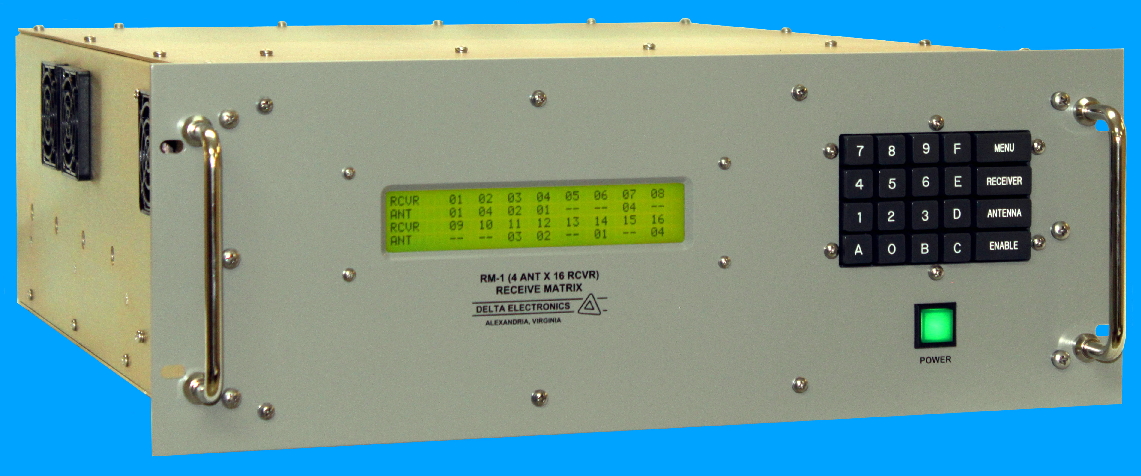 |
Model RM-1 (4 Antenna by 16 Receiver) HF Receive Matrix

|
|
Each antenna input is buffered and amplified by a multiple-output multicoupler to provide an isolated antenna signal for each receiver. Multiple-input selector switches, one for each receiver, select the specified antenna signal for connection to the associated receiver. This multicoupler/selector switch design provides a full fan-out, nonblocking switch matrix for connecting any combination of receivers to any antenna.
The multicoupler utilizes a low noise wideband amplifier to drive the RF distribution circuits. This design permits operation in the presence of high intensity RF signals with minimal intermodulation distortion, noise, sensitivity to undesired signals and excellent output-to-output and output-to-input isolation. The selector switches use reed relays to interconnect the RF circuits. Extensive life testing of the reed relays demonstrates RF contact life in excess of 50 million operations with +19 dBm (2 Vrms) signals.
The RM-1 may be remotely controlled via RS-232 serial data interface to either the Delta Model MCU-9 Matrix Control Unit or a customer supplied communication system computer/controller. Optional RS-422 and Ethernet interfaces are available. The RM-1 provides a nonvolatile memory to retain existing switch connection information in the event of power interruption. All switch connections are automatically reestablished upon power restoration. Built-in test equipment monitors amplifier operating points and other important functions and identifies defective assemblies which are easily replaced. The RM-1 may be locally controlled via a front panel keypad and LCD display.
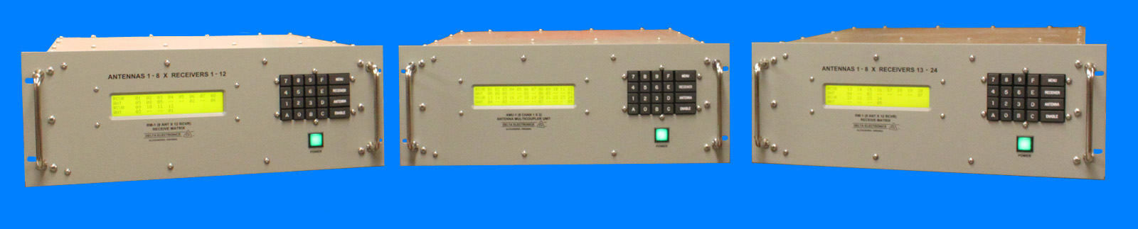
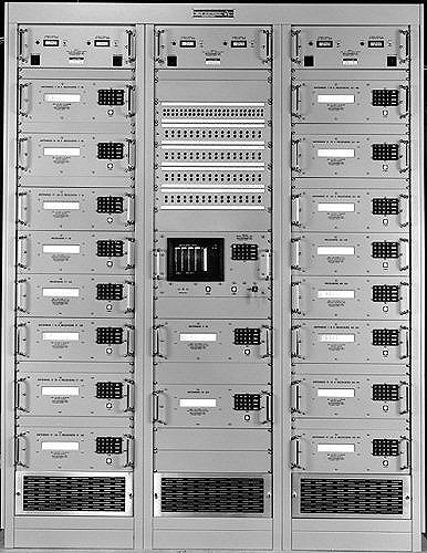
The RM-1 Receive Matrix is also available in a modular and expandable configuration for switching requirements up to 24 antennas by up to 64 receivers. Consult the factory for specifications and capabilities.
8 Antenna by 8 Receiver: This configuration provides locally and remotely controlled RF switching between up to eight antennas and up to eight receivers. Smaller antenna/receiver requirements can be accommodated by subequipping the unit with the number of modular antenna multicoupler assemblies or the number of modular receiver selector assemblies required.
4 Antenna by 16 Receiver: This configuration provides locally and remotely RF controlled switching between up to four antennas and up to sixteen receivers. Smaller antenna/receiver requirements can be accommodated by subequipping the unit with the required number of modular assemblies.
The RM-1 Receive Matrix
modular design enables larger
switching configurations up to 24 antennas by up to 64 receivers.
Custom single chassis configurations developed include the RM-1 (10
Antenna by 8 Receiver) and the RM-1 (12 Antenna by 4 Receiver).
Multiple unit systems developed include the RM-1 (8 Antenna by 24
Receiver), the RM-1 (24 Antenna by 32
Receiver) and the RM-1 (24 Antenna by 64 Receiver). Consult the factory
for specifications and capabilities.
The standard RM-1 serial interface is a half duplex serial data bus per EIA-RS-232 using ASCII characters for control and status information. The standard serial data format employs two digit receiver numbers and two digit antenna numbers. The receive matrix remote control and status format is similar to the transmit matrix control format used with the Model MCU-8C/MCU-9C Matrix Control Units.
Control and Status Word Formats
The
control and status words received and transmitted by the RM-1 follow
the format detailed below. All characters in the control and status
words are ASCII characters. The format shown applies to the 4 Antenna
by 16 Receiver configuration. Format for 8 Antenna by 8 Receiver
configurationis similar except Complete Status Response reports 8
receivers. Although shown below with spaces between
characters for clarity, all messages are transmitted without
intervening spaces.
A. Connect
Command (Remote control system to RM-1):
CR LF ADRS C R1 R2 A1 A2 X
B. Disconnect
Command (Remote control system to RM-1):
CR LF ADRS D R1 R2 X
C. Status
Command (Remote control system to RM-1):
CR LF ADRS S R1 R2 X
D. Status
Response (RM-1 to remote control system):
CR LF ADRS S R1 R2 A1 A2 F M ETB
E. Complete
Status Command (Remote control system to RM-1):
CR LF ADRS S A L L
X
F. Complete
Status Response (RM-1 to remote control system):
CR LF ADRS S R11 R12
A1 A2 R21 R22 A1 A2
R31
R32 A1 A2 R41 R42
A1 A2
R51
R52 A1 A2 R61 R62
A1 A2
R71
R72 A1 A2 R81 R82
A1 A2
R91
R92 A1 A2 R101 R102
A1 A2
R111
R112 A1 A2 R121 R122
A1 A2
R131
R132 A1 A2 R141 R142
A1 A2
R151
R152 A1 A2 R161 R162
A1 A2
RS AM PS F M ETB
The
characters are defined as follows:
CR
=
ASCII Carriage Return
LF
=
ASCII Line Feed
ADRS = RM-1 Address (Front Panel Selectable); Valid addresses are ASCII
characters 0 through 9, A
through F
D
=
Command Designator for Disconnect Message
S
=
Command Designator for Status Message
ALL
=
ASCII Character String Meaning All Receivers
R1
=
Most Significant Digit of Receiver Number
R2
=
Least Significant Digit of Receiver Number
A1
=
Most Significant Digit of Antenna Number
A2
=
Least Significant Digit of Antenna Number
R11
thru R161
=
Most Significant Digit of Receivers 1 through 16,
respectively
R12
thru R162
=
Least Significant Digit of Receivers 1 through 16,
respectively
RS
=
Receiver Selector Fault Digit
AM
=
Antenna Multicoupler Fault Digit
PS
=
Power Supply Control Fault Digit
F
=
Fault Digit
0 = No Fault
1 = Summary Fault
3 = Connection Fault
M
=
Mode Digit
0 = Local Mode
1 = Remote Mode
X
=
ASCII X to End Command Message
ETB
=
ASCII End of Transmission Block to End Status Response
| Standard Configurations: | 8
Antennas by 8 Receivers or 4 Antennas by 16 Receivers |
|
Switch Type: |
Active Full Fan-Out Nonblocking |
|
Characteristic Impedance: |
50 Ohms |
|
Frequency Range: |
2 MHz to 32 MHz with standard bandpass filters 0.5 MHz to 32 MHz with optional low pass filters |
|
Insertion Gain: |
1 dB ±2 dB |
|
Input/Output VSWR: |
1.5:1 Maximum |
|
Isolation: |
Input/Unselected Output: Output/Unselected Input: Output/Output (Common Input): Typical: Minimum: Input/Input: |
50 dB 60 dB 55 dB 45 dB 60 dB |
Switching Speed: |
50 ms Maximum |
|
Noise Figure: |
8 dB Maximum |
|
Intermodulation Distortion: |
Suppression of 2nd and 3rd order intermodulation products better than 50 dB below two 0 dBm signals |
|
Maximum RF Input Signal: |
1 Vrms (+13 dBm) |
|
RF Contact Life: |
>50 x 106 operations at +19 dBm signal levels |
|
Filter Performance: |
Standard Bandpass filter provides minimum of 60 dB rejection below 1.5 MHz and minimum of 40 dB rejection above 45 MHz. Optional Low Pass filter provides minimum of 40dB Rejection above 45 MHz |
|
RF Connectors: |
Antennas: Type N Receptacle Receivers: Type BNC Receptacle |
|
| Control: | Remote: Standard RS-232 Serial Data Interface Optional RS-422 or Ethernet Interface |
|
| Local Status Display: | 40 characters by 4 line liquid crystal display (LCD) provides tabular display of receiver and antenna status |
|
Serial Data Interface: |
RS-232 or RS-422, baud rate selectable in standard increments from 50 through 19200 baud. |
|
Error Detection: |
Parity, framing and overrun error detection prevents faulty operation of coaxial relay |
|
Input Power: |
120 VAC, 50/60 Hz @ 6.25 Amps 240 VAC, 50/60 Hz @ 3 Amps |
|
Environmental: |
Temperature, Operation: 0 to +50° C Temperature, Storage: -30 to +71° C Humidity: 0 to 95% noncondensing |
|
Dimensions and Weight: |
7" (178 mm) high x 19" (483 mm) wide x 24" (610 mm) deep, 37.25 pounds (16.9 kg) |
|
| Delta Electronics, Inc. 5730 General Washington Drive P. O. Box 11268 Alexandria, VA 22312 |
Phone: (703) 354-3350 U.S. Toll Free: 1-800-8-DELTA-8 (1-800-833-5828) Fax: (703) 354-0216 www.deltaelectronics.com Email: sales@deltaelectronics.com |
| HOME | AM/FM/TV Products | HF/VHF/UHF Products |