
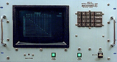
Model MCU-8 Matrix Control Unit
FEATURES
- Microprocessor technology with modular software provides a versatile remote control system for Delta Model SLS Strip Line Switches.
- Standard features include transmitter/antenna circuit display, interlock status display, transmitter/antenna circuit busy protection, automatic antenna grounding and unavailable transmitter/antenna circuit protection.
- Optional features include multiple matrix control and status display, user definable descriptive equipment labels, fiber optic data links, priority protection of transmitter/antenna circuits, and external 14-inch video display unit for auxiliary status display.
|
- Available as either an extended Local Unit only, as a complete Local/Remote Control System with internal modems, RS-232 or RS-422 modem interface, or as a Local Control Unit with RS-232/RS-422 interface to a computer control system.
- Provides remote control and status display of receive matrix systems, either as a dedicated receive matrix system or as a combined transmit matrix/receive matrix control system.
- Adaptable to remotely control and report status of balanced line switches, antenna slew switches, rotatable antennas, power meters, and transmitter operational modes.
| |
Introduction
The Model MCU-8 Matrix Control Unit provides remote control and status display of Model SLS-4M, Model SLS-5M and Model SLS-7M Strip Line Switches. The MCU-8 provides keypad entry of the matrix control commands and a video display of the matrix status as either a schematic diagram of the RF paths through the switch matrix for matrix sizes up through 16 inputs by 20 outputs or a tabular listing of the transmitter and antenna connections for larger matrices or multiple matrix systems.
Matrix control commands are entered using transmitter and antenna numeric selections from the keypad. These selections as well as the status of the selected transmitter and antenna are displayed on the video display for confirmation. Operation of the Enable key initiates the interconnection of the selected transmitter and antenna. The indicator harness of the matrix switch is then read and the status display of the MCU-8 is updated. The MCU-8 also displays interlock status, reports interconnection faults, protects active or busy transmitter/antenna circuits and identifies unavailable transmitter/antenna circuits.
MCU-8/Strip Line Switch Interface
The MCU-8 interfaces the motorized crosspoint actuators of the Strip Line Switch with an Actuator Interface Unit (AIU). The AIU decodes the low level row/column select logic from the MCU-8 and provides the high current/high voltage levels and timing signals required to operate the selected crosspoint. The AIU mounts on the matrix switch. The MCU-8 connects to the AIU with two or five 50 conductor cables depending on switch size.
Standard MCU-8 Configurations
The MCU-8 is available in the following basic models:
MCU-8A: This model provides for extended local control of the matrix switch. The system consists of a Local Control Unit with internal video display and keypad and MCU-8/AIU interconnecting cables up to 100 ft (30 m) in length.
MCU-8B: This model provides a complete system for local and remote control. The system consists of a Local Control Unit with internal video display, keypad and control cables, and a Remote Control Unit with internal video display and keypad. The local and remote units include an RS-232 or RS-422 serial data interface in a customized format at standard data rates from 50 to 19200 baud for use with customer supplied modems or radio circuits. Optionally, the units include 300/1200/2400 bps full duplex Bell 103/212A or CCITT V.21/V.22/V.22bis compatible modems. The internal modems are available with either a two wire or four wire interface to the customer supplied voice grade telephone lines or radio circuits.
MCU-8C: This model provides both for local control and for an RS-232 or RS-422 interface to a customer's control system or computer. The system consists of a Local Control Unit with internal video display, keypad and control cables, plus a two-way ASCII data interface in a customized format at standard data rates from 50 to 19200 baud.
Description
Local Control Unit (MCU-8A/8B/8C)
The Local Control Unit provides the matrix control and status display features and interfaces the optional remote control device. The Local Unit interfaces the matrix via the Actuator Interface Unit to provide the desired control of the matrix actuators. The status of the matrix is read from the actuator indicator switches immediately after each matrix operation and periodically (500 msec intervals) between matrix operations so that the current matrix status is always displayed.
The Local Control Unit front panel components consist of the video display, 20-button keypad, an alternate action power switch and a local/remote control keylock switch. The rear panel of the Local Unit provides connectors for interfacing to the Matrix/AIU and the Remote Control Unit or control computer.
When in the Local mode, command selections are made by depressing the Transmitter key, numeric
TX selection keys, Antenna key, numeric ANT selection keys and the Enable key. Matrix operation is completed within 0.7 second after depressing the Enable key.
Matrix Status Schematic Display
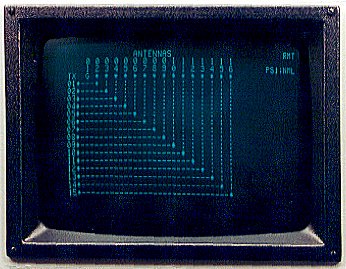 |
The display provides a schematic presentation of the status for matrix sizes up through 16 inputs by 20 outputs, or a tabular display showing transmitter/antenna connections for larger matrices. The tabular display provides both a transmitter status tabulation and an antenna status tabulation. The display updates after each matrix operation and on a periodic basis when the matrix is idle. The bottom line of the display serves as a command line to assist the operator in making selections. Transmitter and antenna selections are displayed as entered and busy or lockout status is shown as applicable. "BPE" indicates that the Enable key will be effective only after operation of the "C" key to override the busy protect feature. After the Enable key is depressed, a "CONFIRM" is displayed to show that the desired switching occurred.
Remote Control Unit (MCU-8B)
This unit provides the same front panel features as the Local Control Unit except for the
LOCAL/REMOTE switch. In the Remote mode, matrix selections are made in the manner outlined above for the Local Unit, with prompting shown on the bottom line of the display. Depressing the Enable key causes the command selections to be sent to the Local Unit, thus enabling matrix operation. Matrix status information is requested from the Local Unit at regular intervals and after each matrix operation. The time required for a complete update of the status display is less than one second for up to 16 transmitters at 1200 baud. Matrix operation will be completed within 0.8 second of depressing the Enable key, and the status display will typically be updated in less than 2.0 seconds at 1200 baud.
Computer Interface (MCU-8C)
The Model MCU-8 Matrix Control Unit may be configured to interface with a communications
center control computer to provide remote control of one or more Delta RF Switch Matrices. Designated as an MCU-8C, this control unit version incorporates all of the local control features of the MCU-8A plus the serial interface circuits and microprocessor program for remote control commands and status responses.
The standard serial interface is per EIA RS-232 and uses ASCII characters for control and status information. RS-422/423/485, IEEE-488 and fiber optic interfaces are also available. Consult factory for optional serial data formats or interfaces.
Standard Serial Interface Characteristics
- Data bits per character: seven
- Start bit: one
- Stop bits (jumper programmable): one (factory program) or two
- Parity (jumper programmable): even (factory program) or odd
- Baud rates (receive and transmit independently switch selectable): 50, 75, 110, 150, 300, 600, 1200, 2400, 4800, 9600 and 19200
- Serial input circuit impedance: 180K Ohm
- Active/tristate serial output circuit (jumper programmable): Serial output circuit is jumper programmable for operation with either a dedicated line or party line (multiple drop) serial communication circuit. When programmed for a dedicated line, the output circuit remains active (-6 Volts) when not transmitting data. When programmed for a party line, the output circuit is normally high impedance (tristate) and switches to an active mode only when transmitting data.
Control and Status Word Formats
| A. | Connect command (remote control system to MCU-8):
CR LF ADRS C T1 T2 A1 A2 X |
| B. | Disconnect command (remote control system to MCU-8):
CR LF ADRS D T1 T2 X |
| C. | Status command (remote control system to MCU-8):
CR LF ADRS S T1 T2 X |
| D. | Status response (MCU-8 to remote control system):
CR LF ADRS S T1 T2 A1 A2 F M I PS ETB |
| E. | Complete status command (remote control system to MCU-8):
CR LF ADRS S A L L X |
| F. | Complete status response (MCU-8 to remote control system) [Actual length of message depends on the maximum number of transmitters]:
CR LF ADRS S T11 T12 A1 A2 I1 . . . T(N)1 T(N) 2 A1 A2 I(N) F M PS ETB |
| G. | Optional antenna ground status command (remote control system to MCU-8):
CR LF ADRS S G N D X |
| H. | Optional antenna ground status response (MCU-8 to remote control system) [Actual length of message depends on the maximum number of antennas]:
CR LF ADRS G A01 A02 . . . A(N) ETB |
The characters are defined as follows:
| CR | = | ASCII Carriage Return |
| LF | = | ASCII Line Feed |
| ADRS | = | MCU-8 address (switch selectable): Any ASCII character except CR, X or ETB (factory set to ASCII 1) |
| C | = | Command sequence designator for connect message |
| D | = | Command sequence designator for disconnect message |
| S | = | Command sequence designator for status message |
| G | = | Command sequence designator for antenna ground status message |
| ALL | = | ASCII character string meaning all transmitters |
| GND | = | ASCII character string meaning antenna ground |
| T1 | = | Most significant digit of transmitter number |
| T2 | = | Least significant digit of transmitter number |
| A1 | = | Most significant digit of antenna number |
| A2 | = | Least significant digit of antenna number |
T11
thru
T(N)1 | = | Most significant digit of transmitters 1 through (N), respectively, where N is the maximum number of transmitters |
T12
thru
T(N)2 | = | Least significant digit of transmitters 1 through (N), respectively, where N is the maximum number of transmitters |
A01
thru
A(N) | = | Antenna ground status digit for antennas 1 through (N), respectively, where N is the maximum number of antennas:
0 = antenna not grounded
1 = antenna grounded |
| F | = | Fault digit:
0 = no fault
1 = summary fault
3 = connection fault
5 = antenna grounding fault (optional) |
| M | = | Mode digit:
0 = local mode
1 = remote mode |
| I | = | Transmitter interlock status digit:
0 = open interlock
1 = valid interlock |
I1
thru
I(N) | = | Transmitters 1 through (N) interlock status digit, respectively, where N is the maximum number of transmitters |
| PS | = | Matrix power supply status digit SLS-4M and SLS-5M:
1 = supply normal
0 = supply fault
SLS-7M:
1 = supplies normal
0, 2 through 7 indicate power supply faults |
| X | = | ASCII X to end command message |
| ETB | = | ASCII end of transmission block to end status response |
Custom Features
The MCU-8 modular software enables adaptation of the program to provide special customer requirements. These custom requirements may be as varied as remote control and status display of receive matrices, descriptive labels for matrices, transmitters, receivers and antennas, automatic switching of inter-matrix trunking, or a real-time clock for preset switching or status logging applications. The MCU-8 may also control and report status of antenna slew switches or rotatable antennas, or monitor and report power meter measurements or transmitter operational modes. These custom features are provided as examples of the MCU-8 flexibility. Consult the factory with your requirements.
Remote Control and Diagnostic Test Software
The remote control and diagnostic software provides control, status display and diagnostic testing of the Delta Electronics, Inc. Model SLS-4M/-5M/-7M Strip Line Switches via the Model MCU-8C Matrix Control Unit. The software operates on an IBM or compatible personal computer with a 286(AT) or higher processor and VGA graphics. The software is available for use with a customer supplied personal computer or as part of a Delta supplied computer system. In addition to providing all the basic control and status features of the MCU-8 unit, the software enhances the control capabilities by using mouse-driven equipment selection routines and expands the display capabilities to include large matrix schematic diagrams and equipment labels. The program also provides diagnostic routines to automatically test remote matrix operation capabilities and to isolate faults to the line replaceable unit (LRU) level. Preset switch configurations establishing multiple transmitter/antenna connections may be defined, stored and automatically implemented. All switch configuration changes, status reports, and diagnostic test results may be logged on the system printer. Optional program modules provide control and status reporting of other communication station facilities including rotatable log periodic antennas, receive matrices, transmitters, receivers, and site security equipment.
Logistic Data
Logistic data available for the Model MCU-8 Matrix Control Unit includes provisioning data, spare parts lists, factory training, reliability and maintainability analyses, safety studies, and technical manual documentation. Most line replaceable units for the control unit are provisioned and assigned National Stock Numbers.
SPECIFICATIONS
| Number of Transmitters: | Up to 16 (schematic status display)
Up to 40 (tabular status display) |
| Number of Antennas/Loads: | Up to 20 (schematic status display)
Up to 40 (tabular status display) |
Matrix/Transmitter/
Antenna Selection: | Twenty button keypad for selection and command initiation. |
| Status Display: | 9-inch CRT with 22 line by 52 character per line format. Schematic display for up to 16 input x 20 output matrix. Tabular display for up to 40 transmitters and 40 antennas and for multiple matrix status summaries. |
| Data Interface: | MCU-8C and MCU-8B: RS-232 or RS-422 interface, baud rate selectable in standard increments from 50 through 19200 baud.
MCU-8B (Optional): Full duplex 300/1200/2400 bps Bell 103/212A or CCITT V.21/V.22/V.22bis compatible modems |
| Error Detection: | Parity, framing and overrun error detection prevents faulty operation of matrix and errors in status display. |
| Matrix Operate Time: | Local Unit: Less than 0.7 second after initiating the Enable key command (includes switching for SLS-4M/5M/7M).
MCU-8B Remote Unit: Less than 0.8 second (1200 baud) after initiating the Enable key command.
MCU-8C Local Unit: Less than 0.7 second after receiving a valid connect or disconnect command. |
Confirm Time
(16 x 16 Matrix): | Local Unit: Less than 1.0 second after initiating the Enable key command.
MCU-8B Remote Unit: Less than 1.5 seconds (1200 baud) after initiating the Enable key command.
MCU-8C Local Unit: Transmission of status response begins approximately 0.1 second after receiving a status command except during matrix operate and status update sequence. |
Confirm Time
(40 x 40 Matrix): | Local Unit: Less than 1.0 second after initiating the Enable key command.
MCU-8B Remote Unit: Less than 2.0 seconds (1200 baud) after initiating the Enable key command.
MCU-8C Local Unit: Transmission of status response begins approximately 0.1 second after receiving a status command except during matrix operate and status update sequence. |
| Power Requirements: | 120/220/240 VAC ±10%, 50/60 Hz, 50 Watts nominal per unit |
| Dimensions: | 10-1/2" high by 19" wide by 17" deep. Unit includes provision for slide mounting. |
| Weight: | 37 lbs |
| Environmental: | Temperature: 0° C to 50° C
Non-Operating Temperature: -62° C to +70° C
Humidity: 0% to 90% noncondensing |
| Interconnecting Cable: | For interface of Local Control Unit and Matrix AIU. Standard 100 ft (30 m) cable and connectors provided. Longer cable assemblies up to 300 ft (100 m) or fiber optic data links are optionally available. |
| External Video Display Unit: | 10-1/2" high rack mounting with 14" display. Composite video input with loop-through or internal 75 ohm termination. 120/220/240 VAC, 50/60 Hz. (Not included in standard system) |
|
For additional information on any of our products, please contact Sales to discuss your particular requirements:
Delta Electronics, Inc.
5730 General Washington Drive
P. O. Box 11268
Alexandria, VA 22312 |
Phone: (703) 354-3350
U.S. Toll Free: 1-800-8-DELTA-8 (1-800-833-5828)
Fax: (703) 354-0216
www.deltaelectronics.com
Email: sales@deltaelectronics.com |
IBM and AT are registered trademarks of International Business Machine Corporation.
The Delta Electronics logo is a registered trademark of Delta Electronics, Inc.