
Model ASE-1 and ASM-1 C-QUAM®
Stereo Systems
Description
The C-QUAM® Stereo transmission system produces a low distortion AM stereo quadrature modulated signal having superior separation throughout the audio spectrum. The C-QUAM signal is demodulated by envelope detectors to produce a low distortion monophonic audio signal. Stereo receivers demodulate the same signal to full stereo. All listeners receive a clean, low distortion audio signal.
ASE-1 Exciter
The ASE-1 Exciter generates an audio drive signal for the transmitter's modulator and an RF drive signal to replace the transmitter's crystal oscillator output. The resulting transmitter output is a quadrature amplitude modulated signal.
Left and Right audio inputs to the Exciter are equalized and matrixed to produce composite L+R and L-R audio signals.
The L+R audio and a 0º phase shifted carrier are fed to the in-phase suppressed carrier modulator (I).
The L-R audio and a 90º phase shifted (quadrature) carrier are fed to the quadrature suppressed carrier modulator (Q). The 25 Hz pilot tone, used to activate the stereo decoders, is also fed to the Q modulator.
The outputs of the I and Q modulators are summed with the 0º phase carrier to produce a quadrature amplitude modulated (QUAM) signal. A limiter strips the amplitude variations from the QUAM signal, leaving only a phase angle modulated carrier. This carrier is input to the RF chain of the broadcast transmitter, replacing the crystal oscillator signal.
The L+R audio input to the I modulator is also input to the transmitter to amplitude modulate the phase angle modulated carrier to produce the C-QUAM signal.
Envelope detectors sense the AM component of the C-QUAM signal to produce pure, undistorted L+R (mono) audio. Stereo decoders demodulate the C-QUAM signal to derive the L-R and L+R signals. The L-R and L+R signals are combined to generate Left and Right audio signals.
The ASE-1 Exciter circuitry includes all required processing features. Limiters are provided to prevent excessive positive and negative modulation. A blend processor makes high single channel modulation possible by blending a little of each channel with the other. Pre-emphasis is not required.
Large lighted meters and easily accessible controls simplify operation. The meters display either Left and Right audio levels, or L+R and L-R audio levels in dB and percent modulation. A Mode switch selects stereo or mono operation and the pilot switch controls the 25 Hz tone. A Day/Night switch selects one of two audio equalization circuits, adjusted to match separate, alternate transmitters. The equalization circuits can be remotely selected.
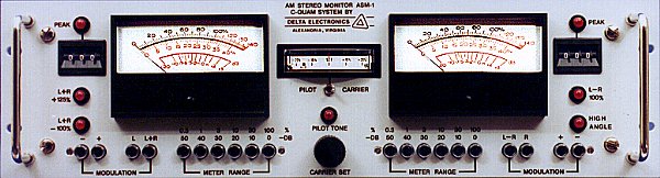
ASM-1 Modulation Monitor
The ASM-1 Modulation Monitor helps maintain and ensure AM broadcast system performance. The Monitor incorporates a high performance C-QUAM decoder to demodulate the RF sample. The Monitor provides all the demodulated signals necessary for annual proof of performance when used with standard AM proof equipment.
The signals available on the rear panel of the Monitor include L+R, L-R, Envelope Detector Output, and Left and Right audio (both balanced and unbalanced). The 25 Hz pilot tone is also available.
Available through front panel meters are: positive and negative L+R, L-R, L and R modulation levels. Peak flashers indicate -100%, +125%, L-R Limit, and negative limit modulation conditions.
Two thumbwheel controlled peak flashers can be set to flash at any level of modulation. The modulation meters and the thumbwheel controlled peak flashers are accessible through rear panel connectors for remote indication.
ASE1ASM1 SPECIFICATIONS
| SYSTEM |
|
| | The following is typical closed loop performance of the Exciter operating into the Monitor.
|
| Stereo Separation at 50% Single Channel: |
40 dB minimum 50 Hz to 5 kHz
30 dB minimum 5 kHz+ to 10 kHz
25 dB minimum 10 kHz+ to 15 kHz
|
| Stereo Separation at 70% Single Channel: | 35 dB minimum 100 Hz to 5 kHz
|
| Frequency Response: |
50 Hz to 10 kHz ±0.5 dB any modulation
10 kHz+ to 15 kHz ±1 dB any modulation
|
| Harmonic Distortion: |
L = R monaural 0.5% maximum at 95% mod.
L = -R pure stereo 0.5% typical at 100% mod.
L, R single channel 1.0% typical at 75% mod.*
* Note: This is equivalent of 140% modulation, 70% envelope modulation, simultaneous with 70% stereo information.
|
| EXCITER |
|
| Audio Input: |
Right 0 dBm to 10 dBm balanced 600 Ohms
Left 0 dBm to 10 dBm balanced 600 Ohms
Both inputs adjustment with factory installed pad per customer requirements.
|
| Meter Functions: | (L + R)Q and (L - R)Q or L and R meter functions switched at the front panel between meters. (L + R)I can be monitored on (L + R) meter by using (L + R) Env switch under the cover on the front panel.
|
| Meter Range: | -20 to +3 dB (0 dB = 100% modulation)
|
| RF Outputs: | Dual Square wave to 38 Vp-p into 50 Ohms. Dual TTL level outputs.
|
| (L + R) Outputs: | Dual output, adjustable under cover on front panel via 10-turn potentiometer up to 16 dBm, 600 Ohms balanced.
|
| Stereo-Monaural: | Switched under cover on front panel. Switches L + R for monaural. Stereo or monaural mode is indicated by LED on front panel. May also be remotely switched via rear panel terminals.
|
| Phase Equalization: | Internal adjustable phase equalization is provided to compensate for phase variations in the transmitter chain. Two paths are available for Day/Night or Main/Aux modes.
|
| Sample Transmitter Output: | A sample transmitter output is provided on the rear panel for diagnostic, comparison of station's transmitter characteristics. This output contains all the modulation aspects (L + R)Q, (L + R)I, and (L - R)Q. Sample transmitter output 2 volts peak-to-peak into 50 Ohms.
|
| MONITOR |
|
| RF Input: |
Frequency crystal controlled
Input level 1 volt to 10 volts RMS
Impedance 50 ohms
|
| Modulation Meters: |
Meter range: 0 to 140%, -20 dB to +2 dB
Attenuator range: 0 to -50 dB in -10 dB steps
Accuracy at 100% modulation 400 Hz: ±2%
Meters switchable to + or - L, R, (L + R), (L - R)
|
| Peak Modulation Indicators: |
| (L + R) Group: |
-100% indicator internally set to flash when modulation exceeds -99%
+125% indicator internally set to flash when modulation exceeds +124%
Peak indicator adjustable via thumbwheel switches from 30% to 150%
Modulation indicators selectable via pushbutton switches + or -
|
| (L - R) Group: |
Negative limit set internally to flash at 1.46 radians or 83.67º
(L - R) limit set internally to flash when phase modulation exceeds 99%
Peak flasher adjustable via thumbwheel switches for 30% to 125%
|
| Output BNC Connectors on Rear: |
Remote Flashers (L + R), (L - R)
Remote Meters (L + R), (L - R)
Left Audio 600 Ohms balanced and unbalanced
Right Audio 600 Ohms balanced and unbalanced
(L + R), (L - R), and 25 Hz Pilot Tone
|
|
For additional information on any of our products, please contact Sales to discuss your particular requirements:
Delta Electronics, Inc.
5730 General Washington Drive
P. O. Box 11268
Alexandria, VA 22312 |
Phone: (703) 354-3350
U.S. Toll Free: 1-800-8-DELTA-8 (1-800-833-5828)
Fax: (703) 354-0216
www.deltaelectronics.com
Email: sales@deltaelectronics.com |
C-QUAM is a registered trademark of Motorla, Inc.
The Delta Electronics logo is a registered trademark of Delta Electronics, Inc.